Friday 3 October 2014

Thyratron Tesla Coil Update

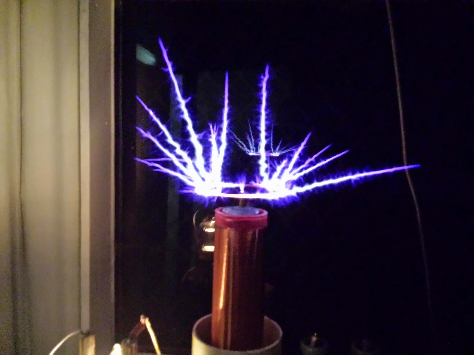
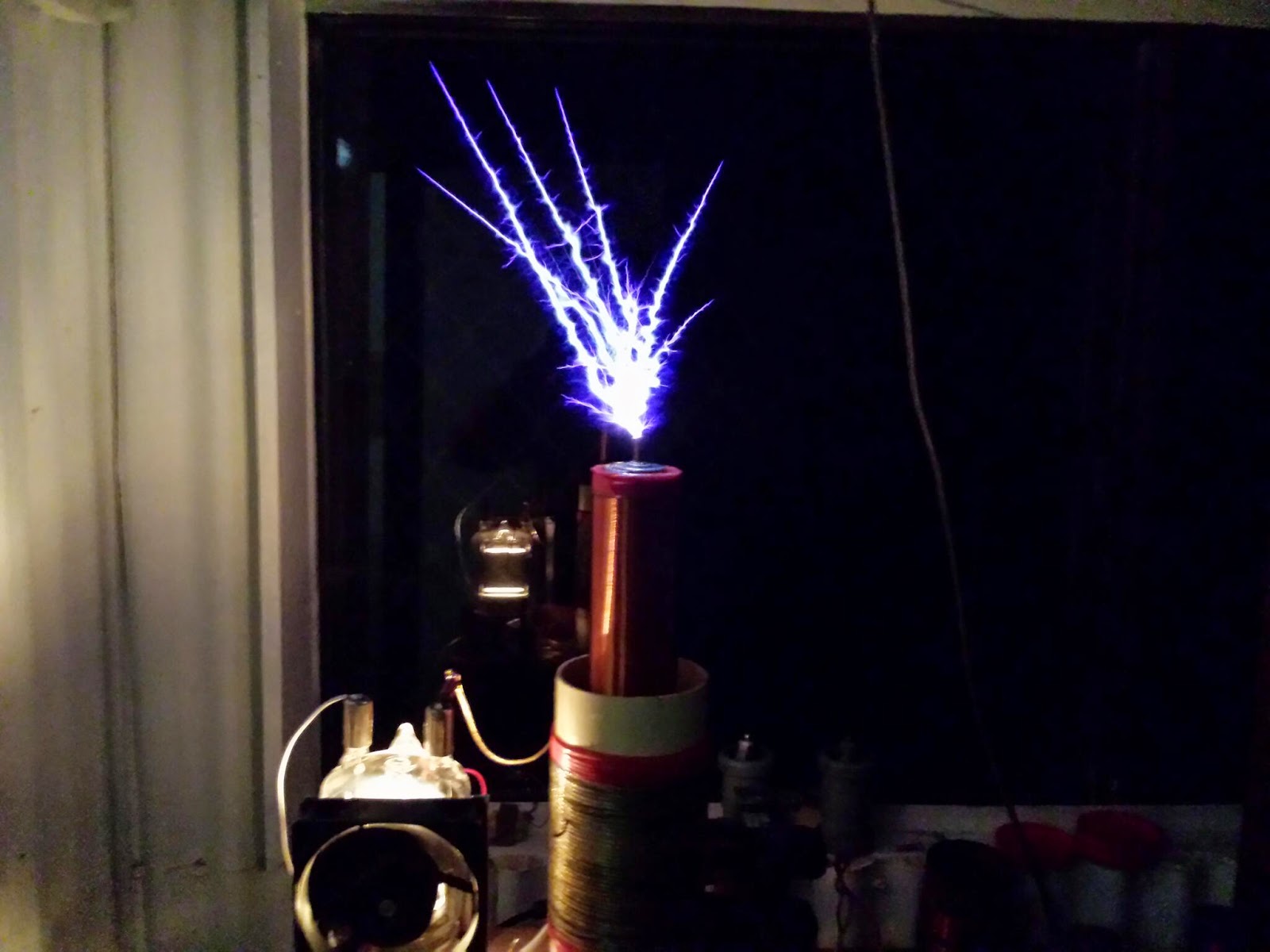
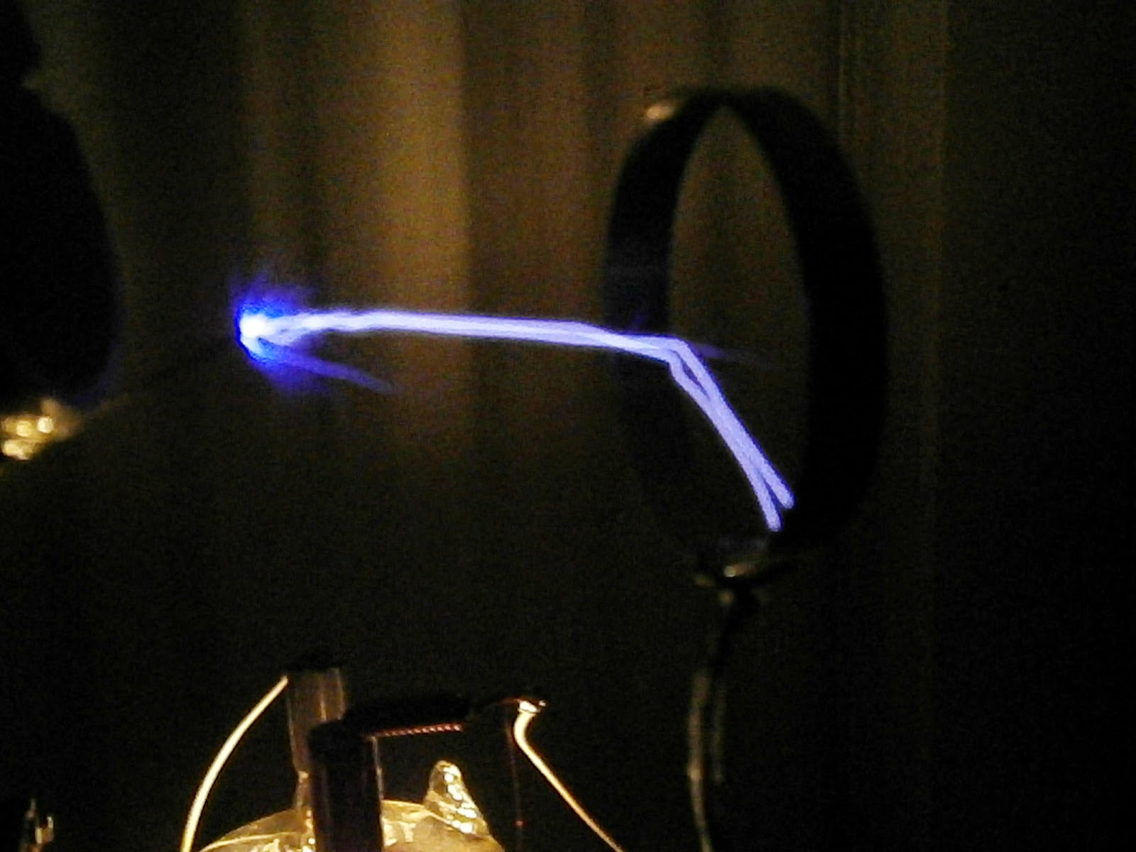
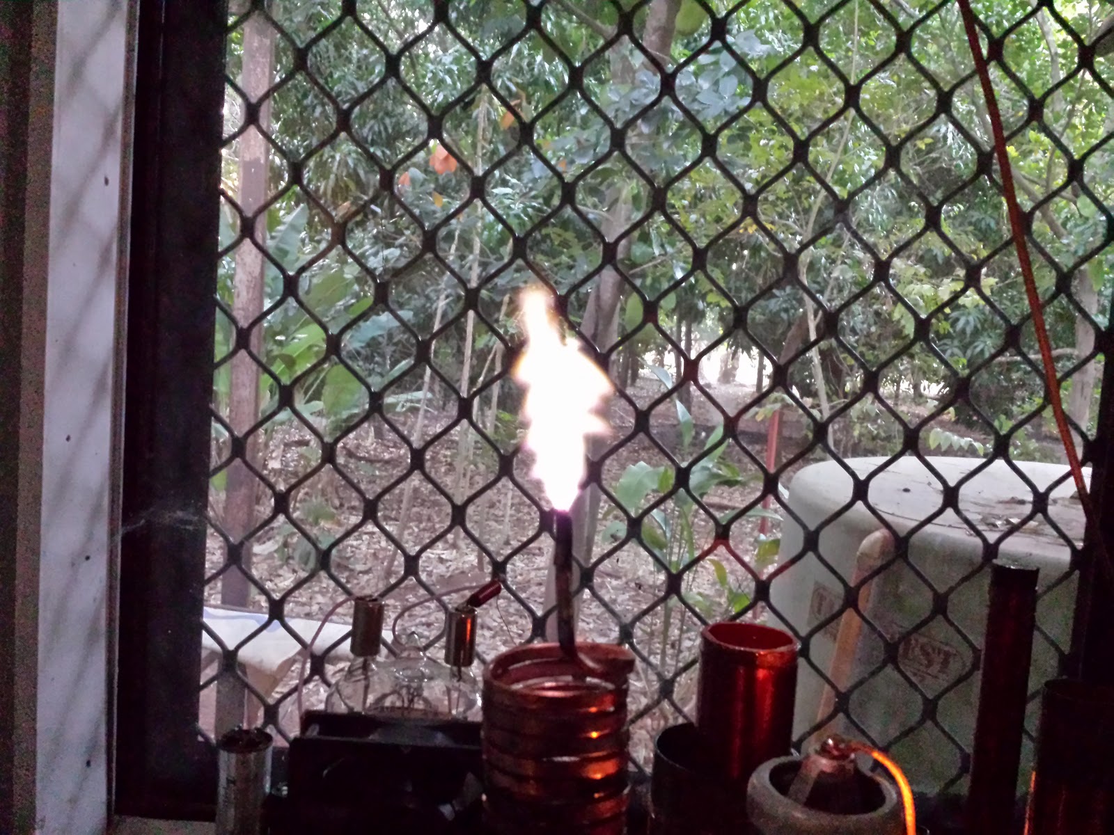
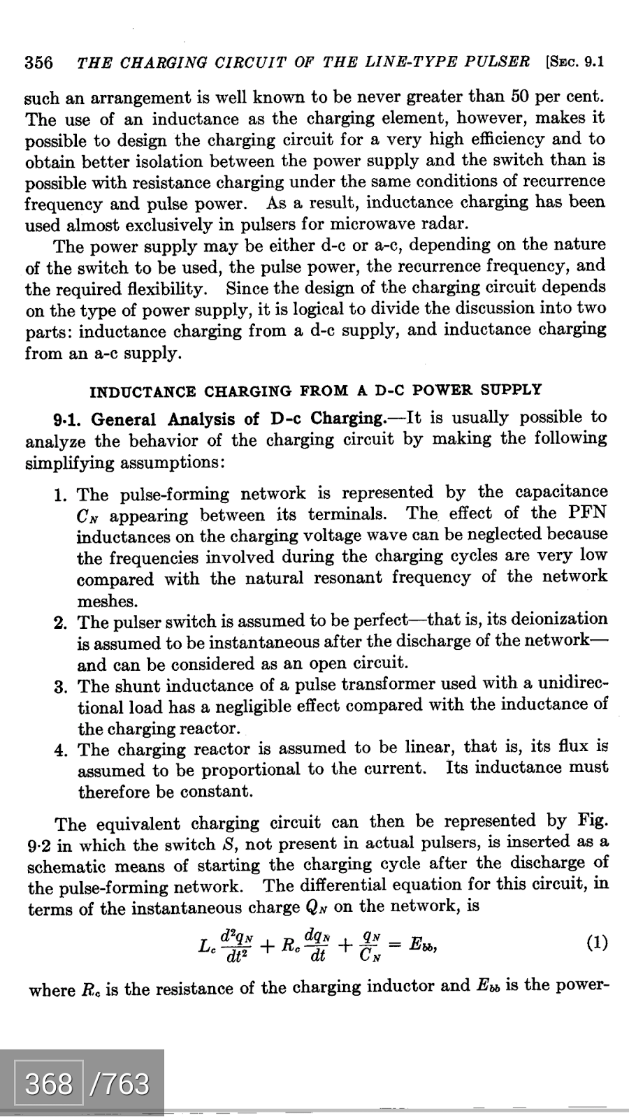
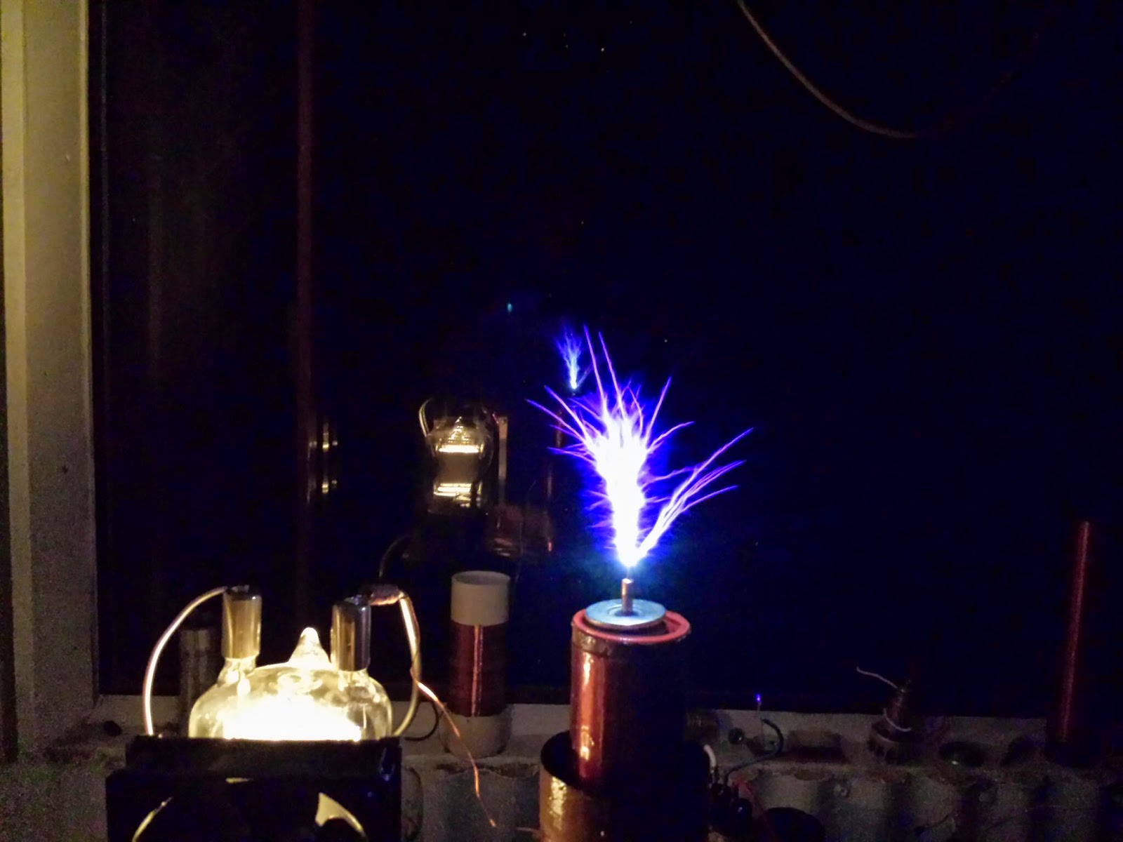
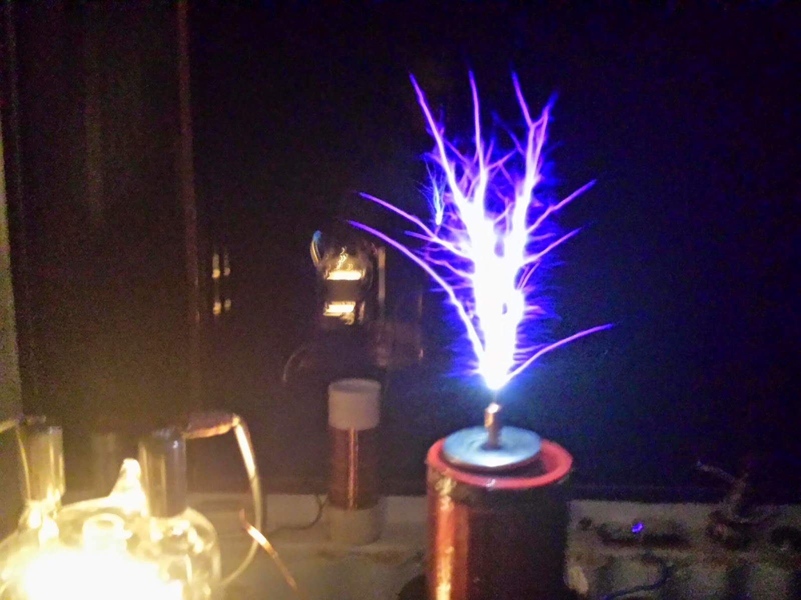
Thyratron Tesla Coil Mk 2: http://youtu.be/Oj4p1HHqzk8

Got it going again with new pulse caps.

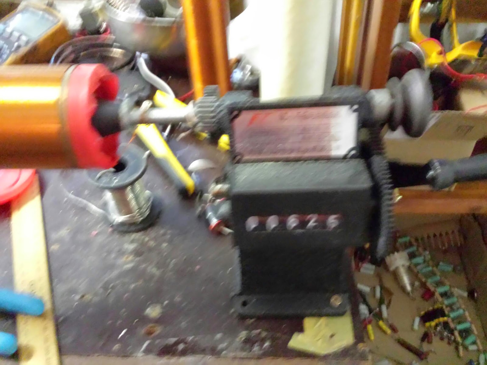
But then my thyratron driver got cooked. The grid to cathode leads were internally arcing.

So I have to do two things:

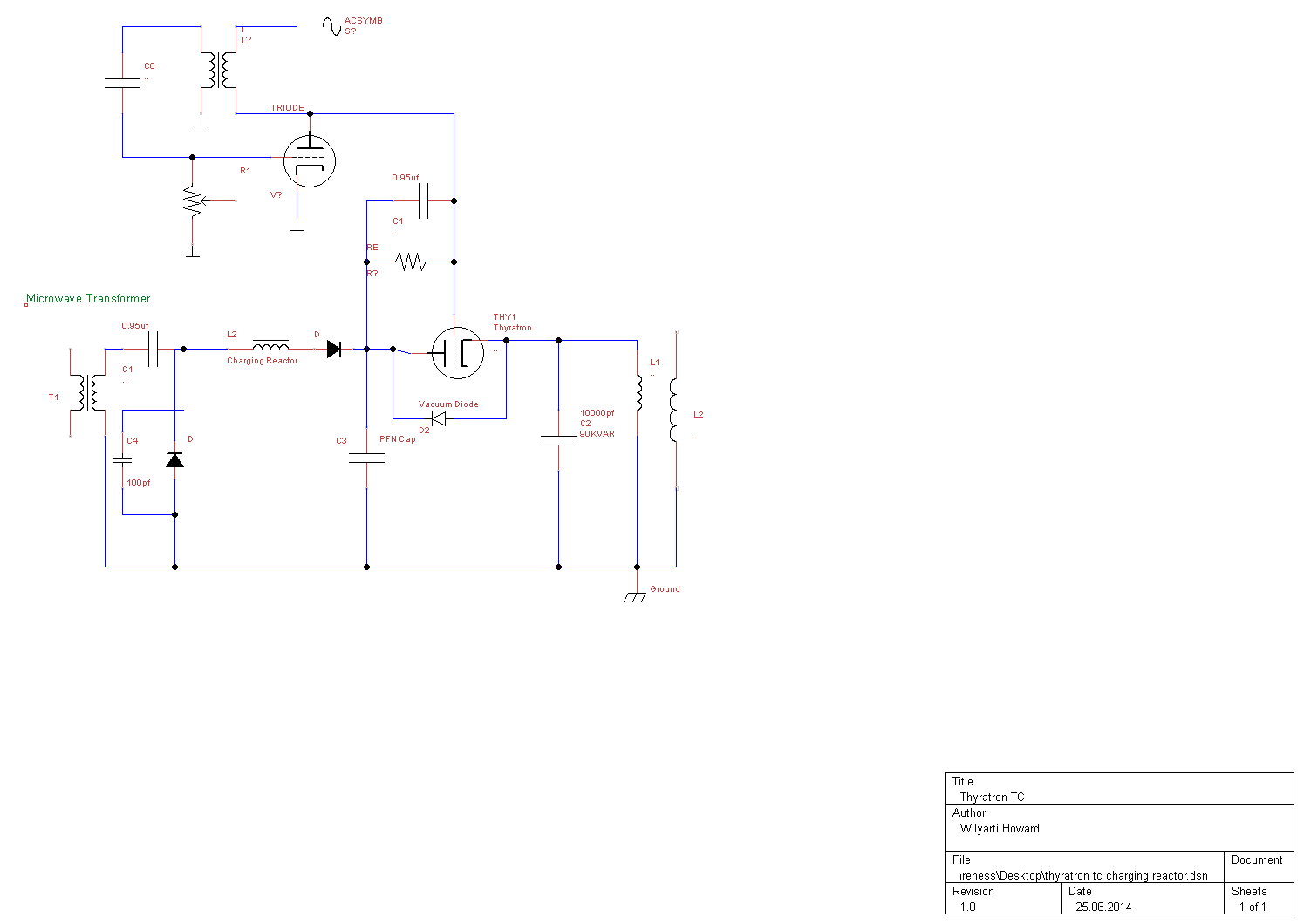
1.) Include reverse voltage bypass over thyratron
2.) Build a microsecond grid bypass circuit to negatively bias grid

I give up for now. This thing is getting way too complicated and expensive.

So if you replicate my experiment you will need a 30kv+ isolated pulse transformer for driving the grid and a grid bias circuit with a nanosecond recovery.

You will also need a nanosecond high voltage reverse protection for the thyratron rated at several hundred watts.

I think all of these things will help.

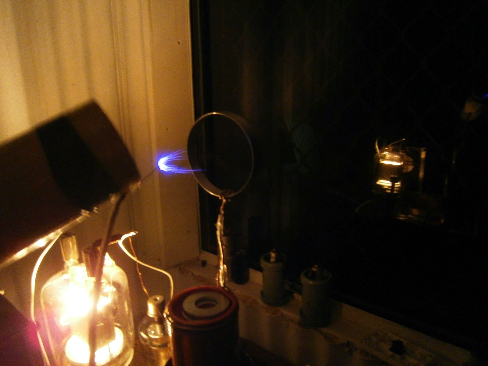
Either that or a thyratron rated at 25kv plus that only supplies 8kv. Even though the input voltage is 8kv the voltage in the tank rises to 50kv+. I get this number based on the 7mm arcs I was getting from the primary to ground.

The pulse repetition frequency needed is between 500 to 1500 pps.

Good luck!

Thyratron Tesla Coil attempt 9

So I just blew up my vintage EG&G thyratron modulator. Stray RF through the thyratron grid cooked the pulse transformer. 

In the pic is my blocking oscillator which I will try to run the system with. Already having arcs through the pulse transformer.

Level of difficulty keeps increasing.  But I keep trying because this thing is a beast when it fires up.

Saturday 27 September 2014

Thyratron Tesla Coil Plans, Theory and Schematics

I achieved success with my Thyratron Tesla Coil getting 10cm streamers before pulse capacitor failure.

Below is the schematic:

Benefits of a parallel LC network:
  1. Reduced load on the thyratron
  2. No need for precise timing
  3. Significant reduction in reverse voltage
  4. Smaller duty cycle on thyratron
  5. Pulse repetition frequency adjustable without effecting tuning

Detrimental effects:
  1. Parallel LC network acts as a short circuit
  2. Increased stress on tank and pulse caps
  3. Less control over the tank circuit
As the thyratron is only dumping energy into the LC network the load across it is reduced. If it were used as a spark gap with reverse voltage bypass the thyratron would have to pass each oscillation between the capacitor and inductor. This could increase thyratron load by a factor of 10 and also risk damage to the cathode and anode if the reverse voltage failed.

One would need to also provide micro second timing to ensure the thyratron fired at the right time to ensure high efficiency and would require complicated and expensive circuitry. This level of difficulty is outside of my range of expertise and it is also highly impractical. Why expose a unipolar switch to bipolar currents?

A parallel LC network is the simplest and easiest way to use a thyratron in a Tesla Coil and it uses the thyratron how it was developed. Namely to switch high voltage DC at high currents over a very short time and then have a very long relaxation period, whilst not being exposed to transients and reverse voltages.

Here is a video of it in operation:


Here are some theory videos I made:
 

Sunday 17 August 2014

Secondary winding jig

Using a coil winder and varnished and sanded mailing tube I built a 600 turn secondary.  0.5mm wire was used.

Achieved 34cm arcs with about 1300 watts.

Saturday 9 August 2014

Vacuum Tube Tesla Coil Schematic VTTC


Above is a schematic for an easily tuned vacuum tube tesla coil. To build the tickler/feedback add a few more turns to the base of the secondary and ground the point they join. The base of the secondary now connects to the grids.

Below is a video of the setup and operation. Power is about 650W.

Update: I achieved 30cm arcs at 1200W with this unit. Arcing to ground will cause serious over voltage on the primary be sure to add a spark gap. Also added a toroid with 10 turns of 5kv wire between the tank circuit and hv out from doubler for emi filtering.

Monday 7 July 2014

New Thyratron Schematic plans

I plan to pulse a TC LC network with a thyratron. The oscillator above the main circuit needs to run through a isolated transformer. I will update the schematic when Iuploaded ow how to build this part.

Smoothed DC will work better than pulsed DC for the supply. The capacitor discharge current should not exceed the thyratrons rating. Power should not exceed thyratrons average current. Reverse diode over thyratron should be a kw vacuum diode or high speed solid state equivalent. 

****update***. I successfully used this circuit to build a thyratron switched tesla coil. See my other blog entries or the pupman.com mailing list for details. I have uploaded a new schematic with revisions and some theory videos plus the a video of it running.

Sunday 6 July 2014

VTTC power measurements

Just got a Energy Cost Meter. Finally have readings on my tesla coil. Filament transformer is drawing over 100VA total power is over 1200VA.

Actual power in is probably a lot less on the output of the mot and the filament transformer. Good to know.

I can now adjust my pf cap. 30uf is too low.

Saturday 5 July 2014

Thyratron TC

Building parts for Thyratron TC, built the isolated transformers and the charging reactor.

The charging inductor or reactor is used to isolate the charging power supply from the thyratron so the thyratron can deionise. 

See pages from Pulse Generators for the full explanation. 

Saturday 28 June 2014

Stable VTTC Single MOT and GU 81m

Finally got power and tuning to enable long runs. Tube glows very dull red after a few minutes run and stabilises with forced cooling. The single mot with doubler doesn't heat up appreciably. Doubler diode is nice and cool as well.

40 turns primary .5mm
12pf 25kv Vacuum Capacitor tank
300 turns secondary .5mm
30 turns .25mm feedback
1kohm grid with 0.01uf mica 6kv
5kv diode 200ma with 3300pf 4kv bypass
0.95 2200vac mot cap in doubler
100pf 25kv ceramic mot bypass cap
Frequency unstable 800khz to 1mhz

Blown up countless diodes and other components. 

One more thing you need a tank capacitor or the primary will resonate with the transformer and the intercapacitance of the tube and pop diodes or short out the transformer.

Going to leave as is with no more mods.

EDIT: After a blown MOT I added a rf filter to the ground of the MOT and used a rf ground for the secondary. I also added 3.3nf 12kv across the MOT. I also addes a safety gap across to MOT for overvoltage protection.  I hope this will be enough rf and overvoltage protection.