Saturday, 27 September 2014

Thyratron Tesla Coil Plans, Theory and Schematics

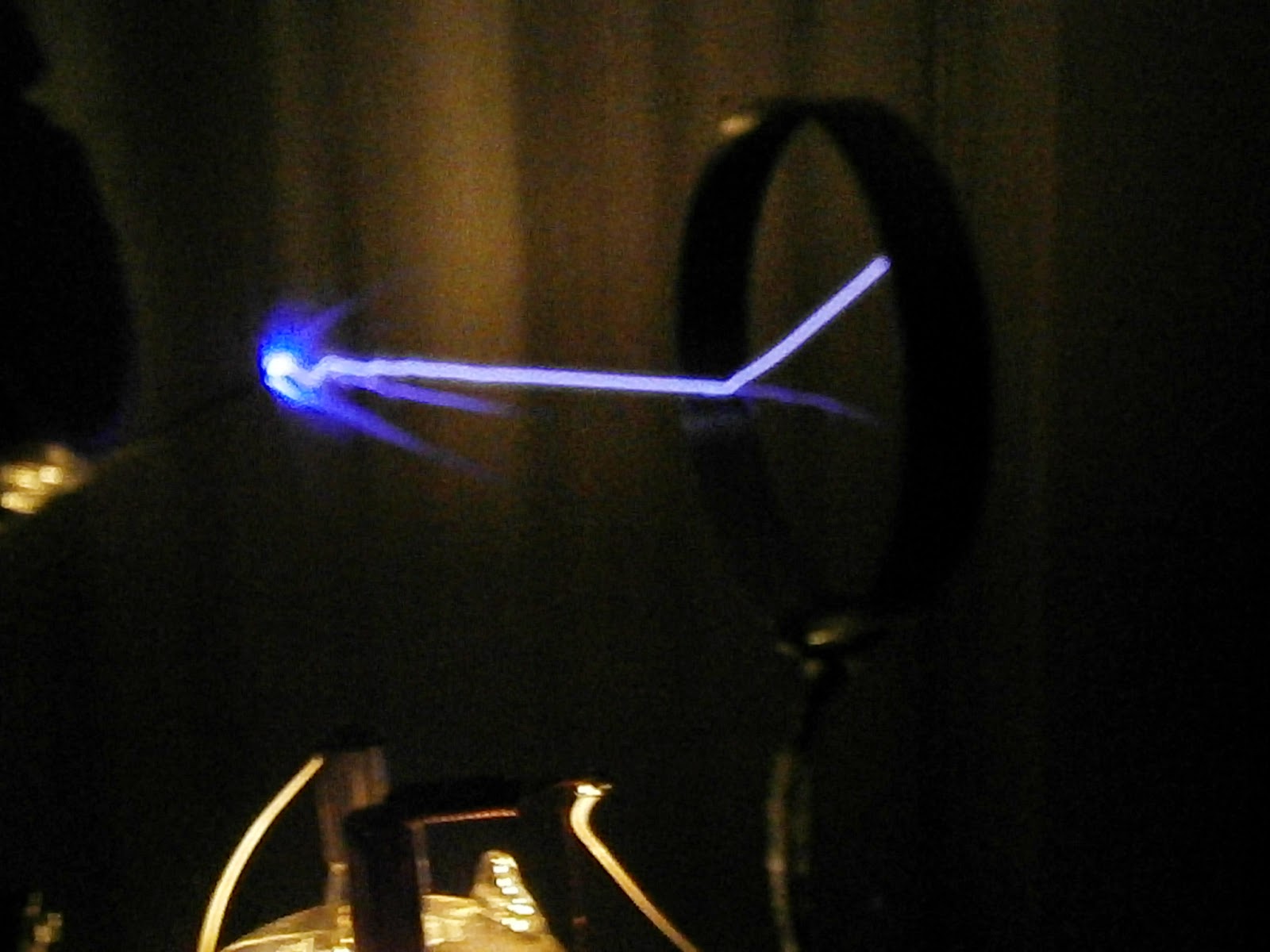
I achieved success with my Thyratron Tesla Coil getting 10cm streamers before pulse capacitor failure.

Below is the schematic:

Benefits of a parallel LC network:
  1. Reduced load on the thyratron
  2. No need for precise timing
  3. Significant reduction in reverse voltage
  4. Smaller duty cycle on thyratron
  5. Pulse repetition frequency adjustable without effecting tuning

Detrimental effects:
  1. Parallel LC network acts as a short circuit
  2. Increased stress on tank and pulse caps
  3. Less control over the tank circuit
As the thyratron is only dumping energy into the LC network the load across it is reduced. If it were used as a spark gap with reverse voltage bypass the thyratron would have to pass each oscillation between the capacitor and inductor. This could increase thyratron load by a factor of 10 and also risk damage to the cathode and anode if the reverse voltage failed.

One would need to also provide micro second timing to ensure the thyratron fired at the right time to ensure high efficiency and would require complicated and expensive circuitry. This level of difficulty is outside of my range of expertise and it is also highly impractical. Why expose a unipolar switch to bipolar currents?

A parallel LC network is the simplest and easiest way to use a thyratron in a Tesla Coil and it uses the thyratron how it was developed. Namely to switch high voltage DC at high currents over a very short time and then have a very long relaxation period, whilst not being exposed to transients and reverse voltages.

Here is a video of it in operation:


Here are some theory videos I made:
 

Sunday, 17 August 2014

Secondary winding jig

Using a coil winder and varnished and sanded mailing tube I built a 600 turn secondary.  0.5mm wire was used.

Achieved 34cm arcs with about 1300 watts.

Saturday, 9 August 2014

Vacuum Tube Tesla Coil Schematic VTTC


Above is a schematic for an easily tuned vacuum tube tesla coil. To build the tickler/feedback add a few more turns to the base of the secondary and ground the point they join. The base of the secondary now connects to the grids.

Below is a video of the setup and operation. Power is about 650W.

Update: I achieved 30cm arcs at 1200W with this unit. Arcing to ground will cause serious over voltage on the primary be sure to add a spark gap. Also added a toroid with 10 turns of 5kv wire between the tank circuit and hv out from doubler for emi filtering.

Monday, 7 July 2014

New Thyratron Schematic plans

I plan to pulse a TC LC network with a thyratron. The oscillator above the main circuit needs to run through a isolated transformer. I will update the schematic when Iuploaded ow how to build this part.

Smoothed DC will work better than pulsed DC for the supply. The capacitor discharge current should not exceed the thyratrons rating. Power should not exceed thyratrons average current. Reverse diode over thyratron should be a kw vacuum diode or high speed solid state equivalent. 

****update***. I successfully used this circuit to build a thyratron switched tesla coil. See my other blog entries or the pupman.com mailing list for details. I have uploaded a new schematic with revisions and some theory videos plus the a video of it running.

Sunday, 6 July 2014

VTTC power measurements

Just got a Energy Cost Meter. Finally have readings on my tesla coil. Filament transformer is drawing over 100VA total power is over 1200VA.

Actual power in is probably a lot less on the output of the mot and the filament transformer. Good to know.

I can now adjust my pf cap. 30uf is too low.